Guidance for Building a High-Performance Numerical Weather Prediction System on AWS
Summary: AWS provides a scalable cloud infrastructure for running numerical weather workloads. With virtually unlimited capacity, you can run your simulations and workloads without the limitations of on-premises high performance computing (HPC) infrastructure.
On AWS, you can deploy flexible HPC cluster configurations that scale up or down based on your workload demands, eliminating long wait times and lost productivity associated with fixed on-premises clusters. Additionally, you can use AWS cloud services for data analytics as well as artificial intelligence and machine learning (AI/ML) to enhance your numerical weather prediction workflows and derive results faster.
This Guidance is designed for users who want to run numerical weather codes on AWS. For customer case studies related to weather HPC workloads on AWS, navigate to AWS HPC Customer Success Stories and select Weather.
Overview
This implementation guide provides a comprehensive step-by-step approach to configuring a highly accurate weather prediction solution using AWS cloud services. By following the detailed instructions, you can provision and integrate AWS ParallelCluster for deploying high performance compute (HPC) environments, Amazon Elastic Compute Cloud (Amazon EC2) HPC nodes for powerful processing, and Amazon FSx for Lustre, enabling rapid data access. With this guide, you can effectively harness the Weather Research & Forecasting Model (WRF) to generate precise forecasts across the continental United States.
Features and benefits
Guidance for Building a High-Performance Numerical Weather Prediction System on AWS provides the following features:
- High-resolution forecasts with AWS ParallelCluster
- Flexible procurement of large amounts of computing resources
- Agile response to load fluctuations
Use cases
For customer case studies related to weather HPC workloads on AWS, navigate to AWS HPC Customer Success Stories and select Weather.
Architecture overview
The architecture diagram below shows how the AWS ParallelCluster UI manages a typical HPC cluster:
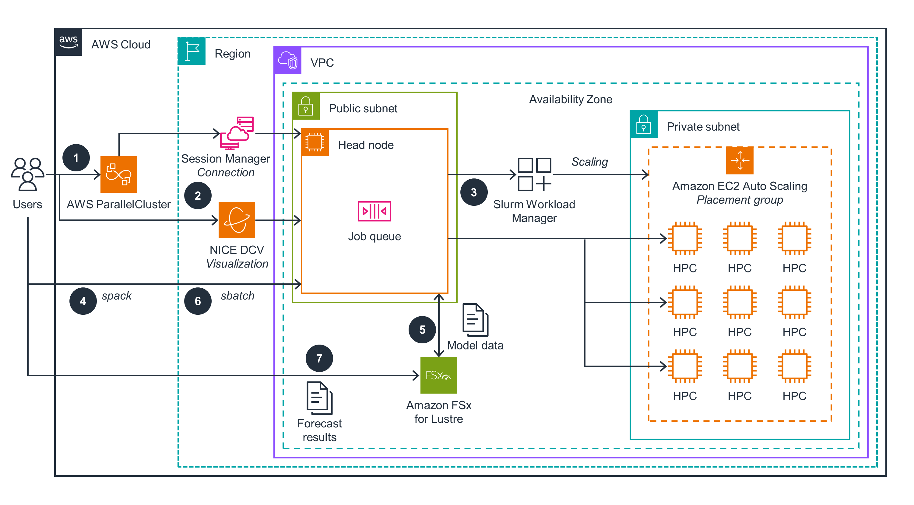
Figure 1: AWS ParallelCluster UI and HPC cluster architecture
Below are steps that both provision the AWS ParallelCluster UI and configure an HPC cluster with compute and storage capabilities:
- Users deploy the AWS CloudFormation stack that provisions networking resources. This includes Amazon Virtual Private Cloud (Amazon VPC), Amazon API Gateway for subnets, Amazon FSx for Lustre for storage, and finally AWS ParallelCluster.
- The ParallelCluster UI endpoint is available for users’ authentication through API Gateway.
- The user authenticates to the ParallelCluster UI endpoint by invoking an AWS Lambda function and handling login details through Amazon Cognito.
- Authenticated users provision HPC clusters through the ParallelCluster UI using the sample cluster specifications available with this sample code for this Guidance. Each HPC cluster has a head node and compute node(s) dynamically provisioned for application workload processing.
- Users authenticated through the ParallelCluster UI can connect to the HPC cluster using AWS Systems Manager Session Manager or through NICE DCV sessions.

Figure 2. HPC cluster architecture and user interactions for running numerical weather prediction on AWS
The following steps are part of the user interactions with the ParallelCluster UI to deploy and run the numerical weather prediction model.
- The user authenticates to the ParallelCluster UI through Cognito, API Gateway, and Lambda.
- The user connects to the HPC cluster through the ParallelCluster UI using a session-type AWS Systems Manager (SSM) connection, or NICE DCV; the latter can be used directly without the ParallelCluster UI.
- SLURM (an HPC resource manager from SchedMD) is installed and used to manage the resources of ParallelCluster, driving resource scaling.
- Spack is a package manager for supercomputers, Linux, and macOS. Once installed, it is used to install necessary compilers and libraries, including the National Center for Atmospheric Research (NCAR) Command Language (NCL) and the Weather Research & Forecasting Model (WRF) model.
- FSx for Lustre storage is provisioned along with HPC cluster resources. Input data used for simulating the Continental United States (CONUS) 12-km model is copied to the /fsx directory that is mapped to that storage.
- Users create an
sbatchscript to run the CONUS 12-km model. Users submit that job and monitor its status through thesqueuecommand. - Weather forecast calculation results are stored locally in the
/fsx/conus_12km/folder and can be visualized using NCL scripts.
AWS services in this Guidance
| AWS service | Description |
|---|---|
| Amazon Virtual Private Cloud (Amazon VPC) | Core Service—provides additional Networking isolation and security |
| Amazon Elastic Compute Cloud (Amazon EC2) | Core Service—EC2 instances used as cluster nodes |
| Amazon API Gateway | Core service—create, publish, maintain, monitor, and secure APIs at scale |
| Amazon Cognito | Core service—provides user identity and access management (IAM) services |
| AWS Lambda | Core service—provides serverless automation of user authentication |
| Amazon FSx for Lustre | Core service—provides high-performance Lustre file system |
| AWS ParallelCluster | Core service—Open source cluster management tool for deployment and management of High Performance Computing (HPC) clusters |
| Amazon High Performance Computing (HPC) | Core service—HPC cluster resource |
| Amazon System Manager Session Manager | Auxiliary service—instance connection management |
Plan your Deployment
Cost
You are responsible for the cost of the AWS services used while running this guidance.
Please refer to the sample pricing webpage for each AWS Service used in this Guidance. Please note that monthly costs assume that an HPC cluster with Head Node of instanceType c6a.2xlarge and two Compute Nodes of instanceType hpc6a.48xlarge with 1200 GB of FSx for Lustre persistent storage provisioned for that cluster that are active 50%. In reality, computeNodes get de-provisonied around 10 min after completing a job and therefore monthly cost would be lower than this estimate.
Sample cost table
The following table provides a sample cost breakdown for an HPC cluster with one c6a.2xlarge Head Node and two Compute Nodes of instanceType hpc6a.48xlarge with 1200 GB of FSx for Lustre persistent storage allocated for it deployed in the us-east-2 region:
| Node Processor Type | On Demand Cost/month USD |
|---|---|
| c6a.2xlarge | $226.58 |
| hpc6a.48xlarge | $2,102.40 |
| FSx Lustre storage | $720.07 |
| VPC, subnets | $283.50 |
| Total estimate | $3,332.55 |
Supported AWS Regions
This Guidance uses EC2 services with specific instances such as hpc6 and FSx for Lustre services, which may not currently be available in all AWS Regions. You must launch this Guidance in an AWS Region where specific EC2 instance types and Fsx for Lustre are available. For the most current availability of AWS services by Region, refer to the AWS Regional Services List.
Guidance for Building a High-Performance Numerical Weather Prediction System on AWS is currently supported in the following AWS Regions (based on availability of hpc6a, hpc7a, and hpc7g instances:
| AWS Region | Amazon EC2 HPC Optimized Instance type |
|---|---|
| ap-southeast-1 | hpc6a.48xlarge |
| eu-north-1 | hpc6id.32xlarge hpc6a.48xlarge |
| eu-west-1 | hpc7a.12xlarge hpc7a.24xlarge hpc7a.48xlarge hpc7a.96xlarge |
| us-east-1 | hpc7g.4xlarge hpc7g.8xlarge hpc7g.16xlarge |
| us-east-2 | hpc6a.48xlarge hpc6id.32xlarge hpc7a.12xlarge hpc7a.24xlarge hpc7a.48xlarge hpc7a.96xlarge |
Security
When you build systems on the AWS infrastructure, security responsibilities are shared between you and AWS. This shared responsibility model reduces your operational burden because AWS operates, manages, and controls the components, including the host operating system, the virtualization layer, and the physical security of the facilities in which the services operate. For more information about AWS security, visit AWS Cloud Security.
AWS ParallelCluster users are securely authenticated and authorized to their roles through the Amazon Cognito user pool service. The HPC cluster EC2 components are deployed into a virtual private cloud (VPC), which provides additional network security isolation for all contained components. A head node is deployed into a public subnet and available for access through secure connections (SSH and NICE DCV). Compute nodes are deployed into a private subnet and managed from a head node through a SLURM package manager. Data stored in Amazon FSx for Lustre is encrypted at rest and in transit.
Deploy the Guidance
Prerequisites
The following prerequisites are required to deploy this Guidance:
- a computer with an internet connection running Microsoft Windows, macOS X, or Linux.
- an internet browser such as Chrome, Firefox, Safari, Opera, or Edge.
- familiarity with common Linux shell commands.
Deployment process overview
Before you launch this Guidance, review the cost, architecture, security, and other considerations discussed in this implementation guide. Follow the step-by-step instructions in this section to configure and deploy the Guidance into your account.
The deployment process for this Guidance process is broken into the following sections:
- Deploy ParallelCluster UI
- Deploy VPC for HPC Cluster
- Create and Connect to HPC Cluster
- Understand the module environment
- Install Spack package manager
- Install NCL
- Install and run a Weather Research & Forecasting (WRF) test simulation model batch job; retrieve and visualize results.
Estimated time to deploy: Approximately 80 minutes
Deploy ParallelCluster UI
The AWS ParallelCluster UI is a web-based user interface that mirrors the AWS ParallelCluster pcluster CLI while providing a console-like experience. You will install and access the ParallelCluster UI in your AWS account.
You will be using an AWS CloudFormation quick-create link to deploy a ParallelCluster UI stack with nested Amazon Cognito, API Gateway, and Amazon EC2 Systems Manager stacks.
- To deploy an instance of the AWS ParallelCluster UI, choose an AWS CloudFormation quick-create link for the AWS Region that you create clusters in. For us-east-2, Quick create stack is a wizard where you provide inputs and deploy the stack. Alternatively, use the button below:

For other Regions, refer to Installing the AWS ParallelCluster UI to access the quick-create links.
On the Create Stack Wizard page, enter a valid email address for Admin’s Email.
A temporary password to access the ParallelCluster UI will be sent to this email address. If you delete the email before you save or use the temporary password, you must delete the stack and reinstall the ParallelCluster UI.
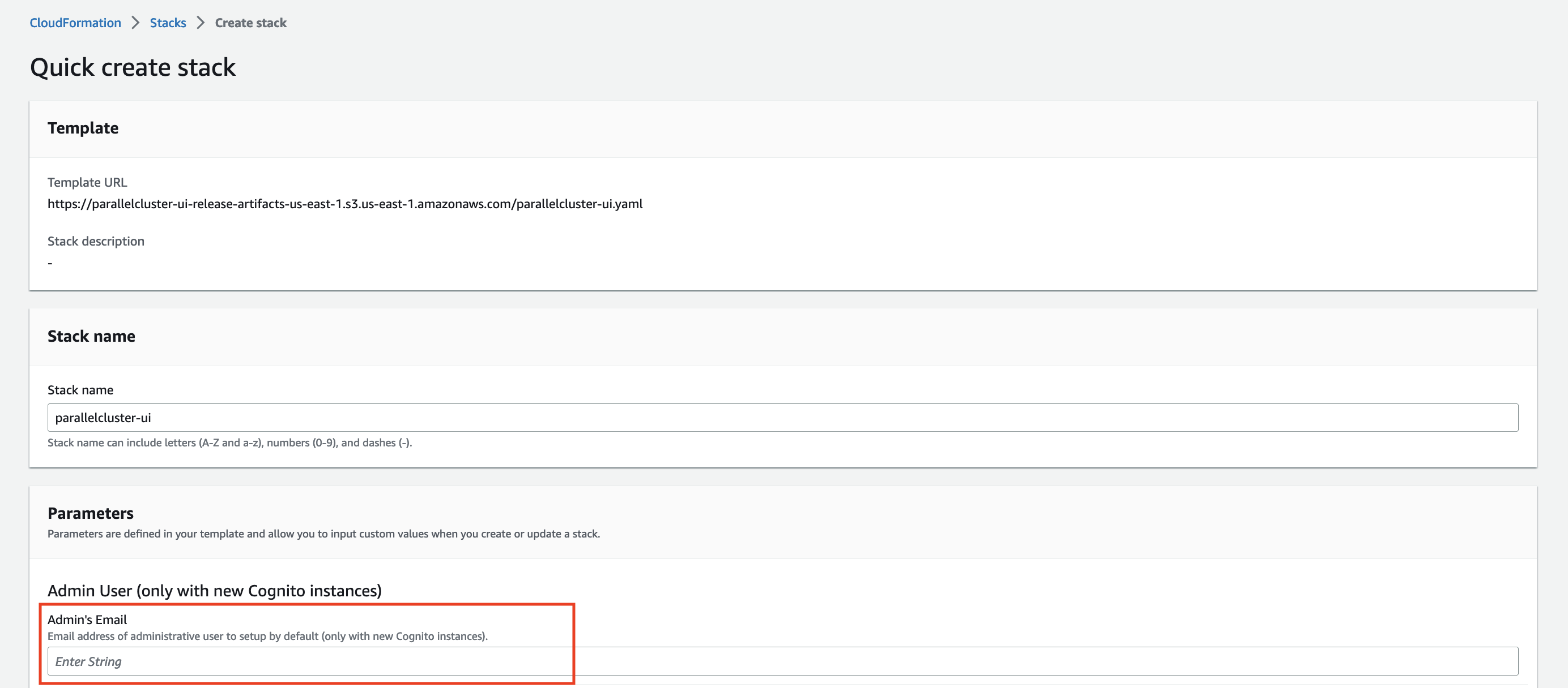
Figure 3. E-mail with a temporary password to access the ParallelCluster UI
- Keep the rest of the form blank. Alternatively, enter values for optional parameters to customize the AWS ParallelCluster UI build.
- Note the stack name for use in later steps (
STACK_NAME).
Locate Capabilities and select the boxes confirming you agree to creating the CloudFormation IAM resources and CAPABILITY_AUTO_EXPAND.
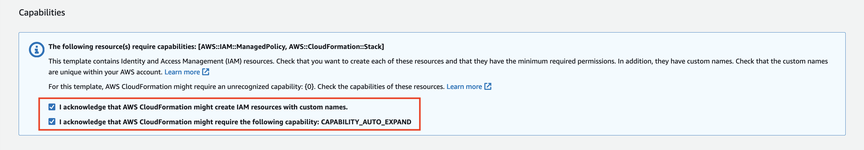
Figure 4. Deployment of the CloudFormation stack
- Select Create stack. It takes about 15 minutes to complete the AWS ParallelCluster API and AWS ParallelCluster UI deployment.
Deploy VPC for HPC Cluster
In order to deploy the HPC head nodes into a defined public subnet and the compute nodes into a private subnet, a VPC is required. Refer to the sample CloudFormation code. This code deploys the the VPC with the required public and private subnets. For instructions on how to create and run a CloudFormation stack from a YAML template, refer to the CloudFormation Get Started guide. Alternatively, the ParallelCluster components can be deployed into an existing VPC.
Login to ParallelCluster UI
After the CloudFormation deployment completes, open the email that was sent to the address you entered for the ParallelCluster
adminuser. It contains a temporary password that you use to access the ParallelCluster UI.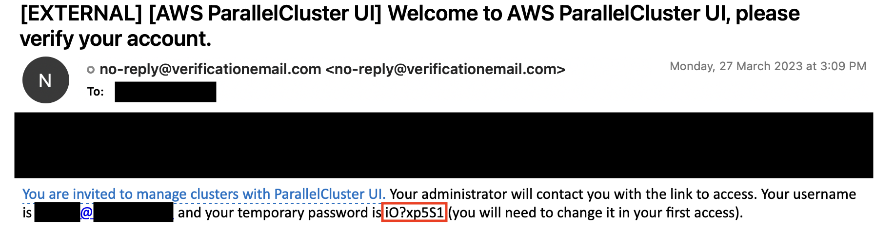
Figure 5. E-mail with a temporary password to access the ParallelCluster UI
In the CloudFormation console list of stacks, choose the link to
STACK_NAME.In Stack Details, choose Outputs and select the link for the key named
STACK_NAMEURL to open the AWS ParallelCluster UI.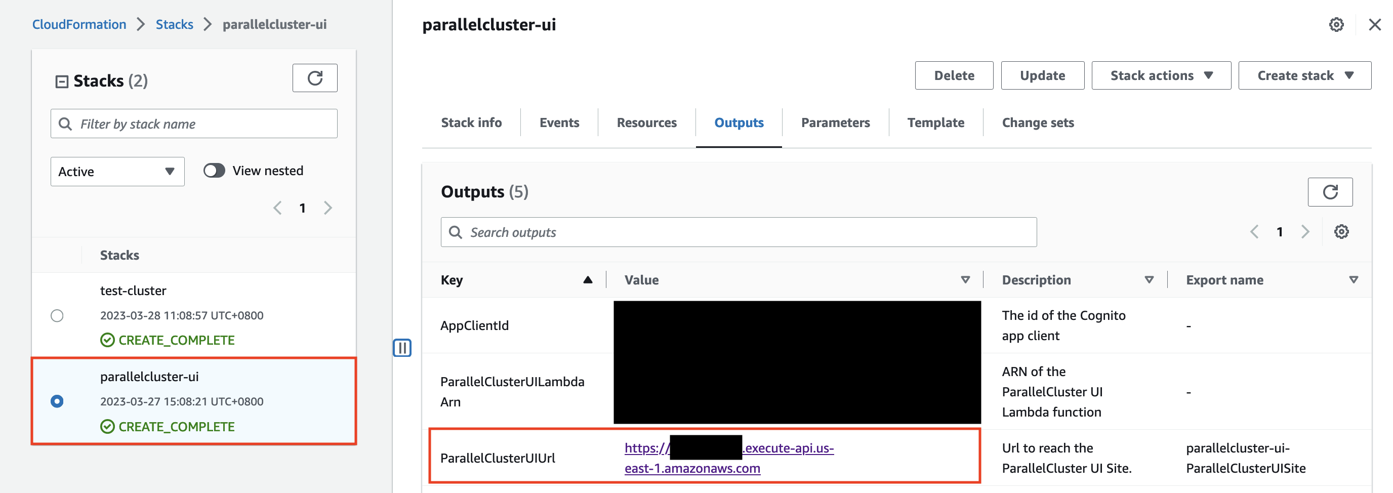
Figure 6. Access ParallelClusterUI URL
Enter the temporary password. Follow the steps to create your own password and log in.

Figure 7. ParallelClusterUI login prompt
You are now on the home page of the AWS ParallelCluster UI in the AWS Region that you selected.
Create and connect to the HPC cluster
In this section, you are going to use the ParallelCluster UI to create a cluster from a sample template we’ve provided.
Use the hpc6a instance. It is an AMD EPYC (Milan) processor. The hpc6a instance is designed specifically for tightly coupled HPC-style workloads.
The instances in that family have the following resource specifications and costs:
| Instance Size | Cores | Memory (GiB) | EFA Network Bandwidth (Gbps) | Network Bandwidth (Gbps)* | On-Demand Price |
|---|---|---|---|---|---|
| hpc6a.48xlarge | 96 | 384 | 100 | 25 | $2.88 |
| c6a.48xlarge | 96 | 384 | 50 | 50 | $7.344 |
Download the Cluster Configuration Template.
In the home page of the AWS ParallelCluster UI, locate Clusters, and select
us-east-2as your Region then choose Create cluster.
Figure 8. Create HPC cluster-Region selection.
In Cluster name:
Enter a name for your cluster (
CLUSTER_NAME).Select Existing template and choose Next.
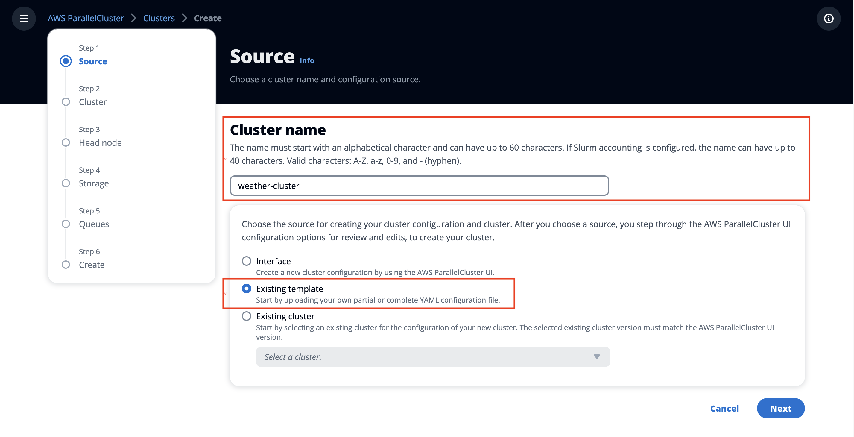
Figure 9. Create an HPC cluster-specify the cluster name.
You will be prompted to provide a file. Select the cluster configuration file that you downloaded in step 1 above, which is titled either
cluster-config-c6a.yamlorcluster-config-hpc6a.yaml.
In the Cluster section, select a VPC from your account (deployed by the CloudFormation template earlier) and choose Next.
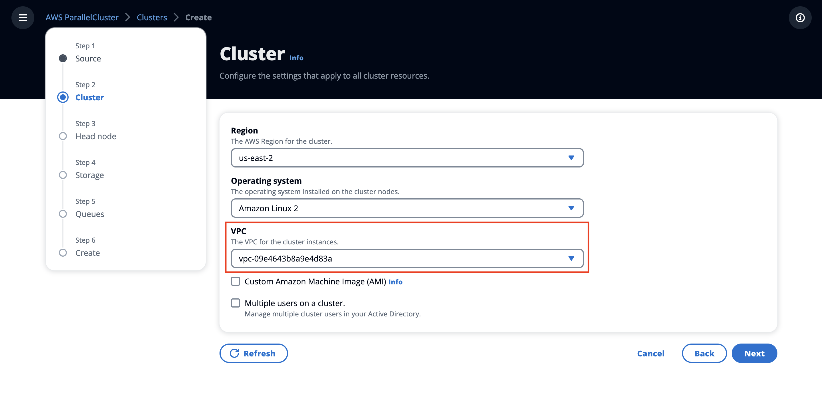
Figure 10. Create an HPC cluster-specify VPC.
- In the Head Node section:
Select a subnet from the Availability Zone ID use2-az2. This was created previously for the Deploy VPC for HPC Cluster section.
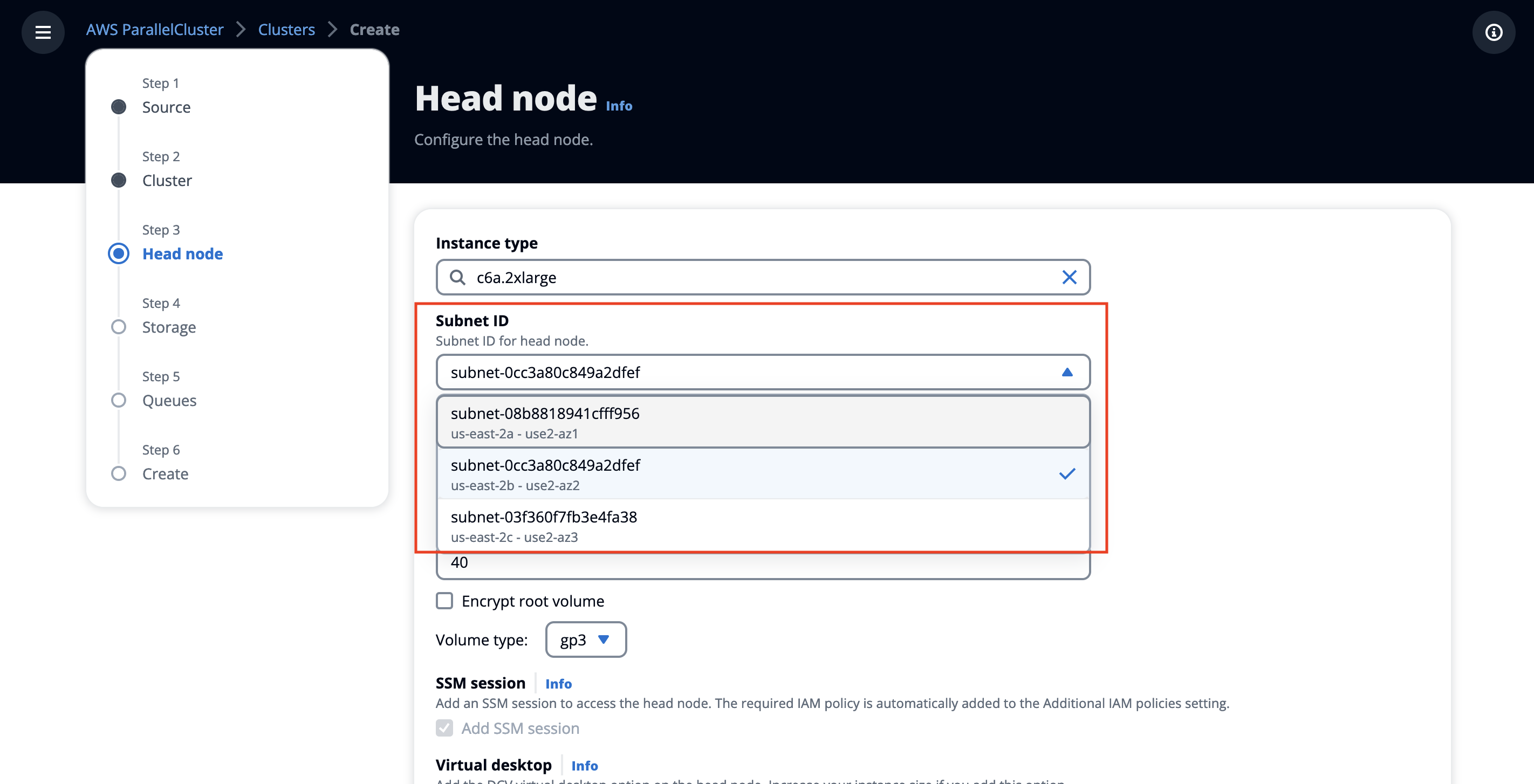
Figure 11. Create an HPC cluster-specify head node subnet.
(Optional) Select a keypair from your account.
Choose Next.
In the Storage section, make sure that Amazon FSx for Lustre and /fsx mount points are selected, and choose Next.
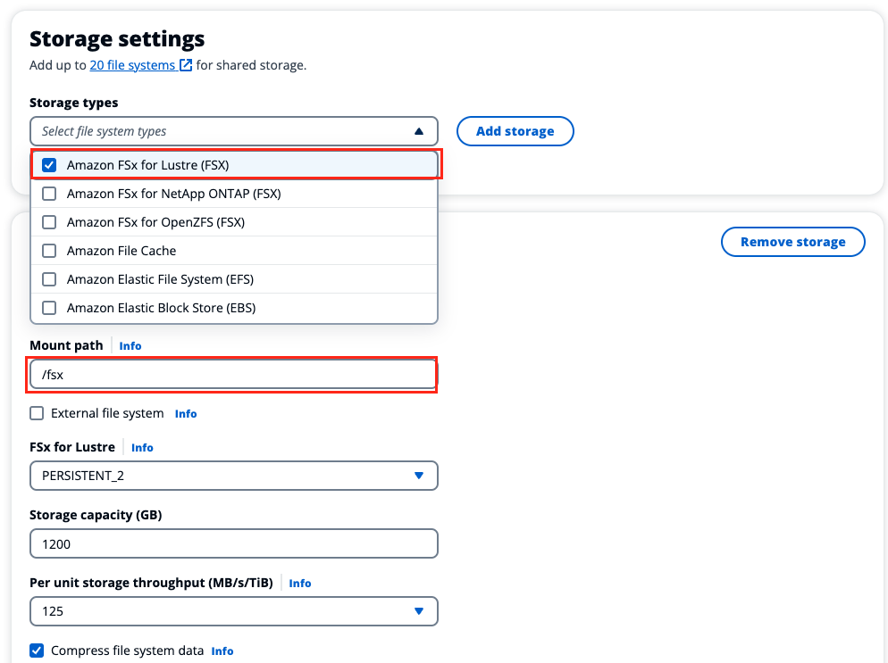
Figure 12. Create an HPC cluster-specify storage.
In the Queues section, under the Compute queue, select the same subnet as in the previous step, then choose Next.
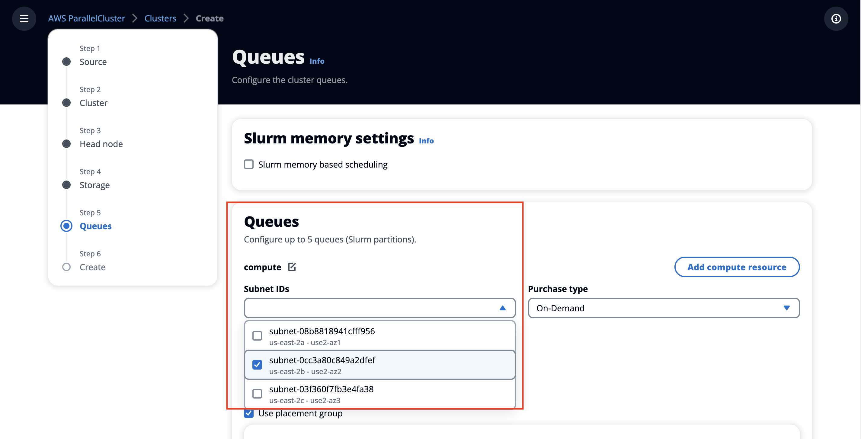
Figure 13. Create an HPC cluster-specify the queue subnet.
Make sure that both the Use Placement Group and the Use EFA options are checked, as shown below:
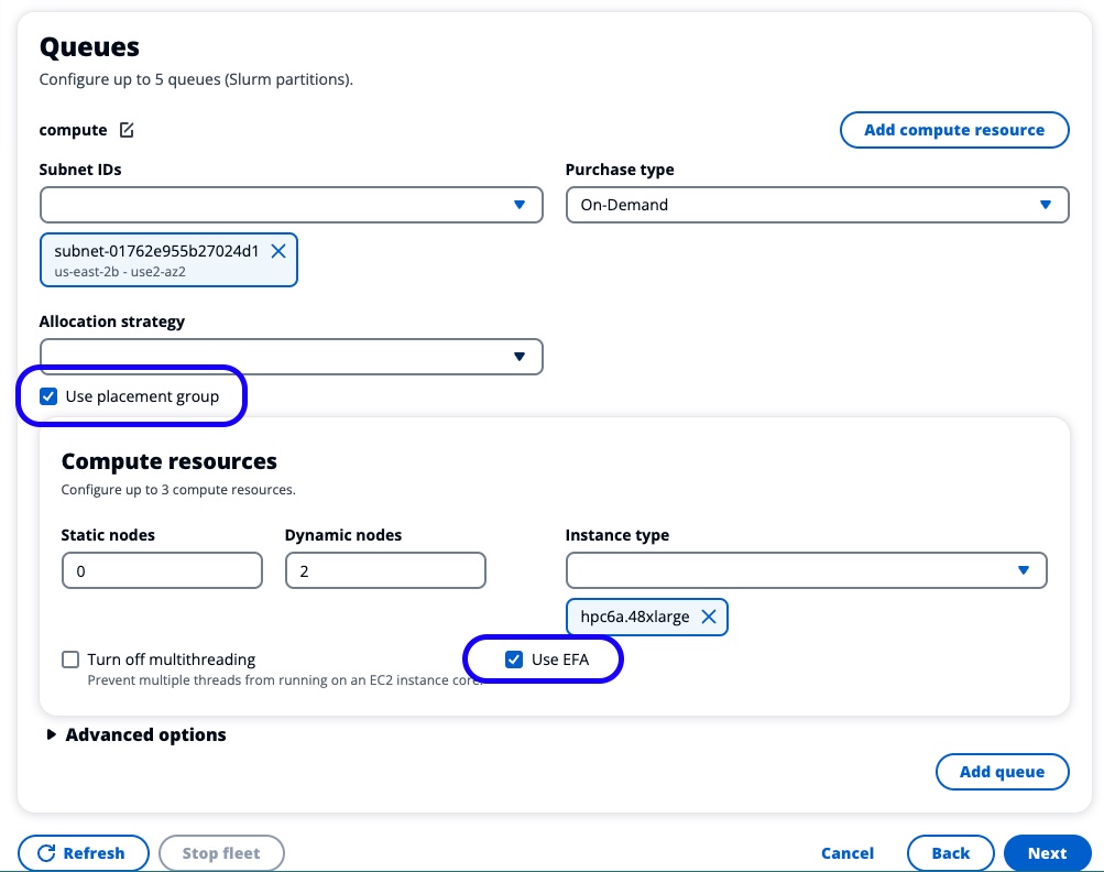
Figure 14. Create an HPC cluster-check placement group and EFA settings.
- In the Create section:
Choose Dry run to validate your cluster configuration and confirm there are no configuration errors.
Choose Create to create your HPC cluster based on the validated configuration.
- After a few seconds, the AWS ParallelCluster UI automatically navigates you back to the Clusters page where you can monitor the
cluster createstatus and stack events. If you do not see your cluster being created, ensure that you have theus-east-2AWS region selected.
Choose Instances to see the list of EC2 instances and its status.
Choose Details to see cluster details, such as the version, status, and a link to the CloudFormation stack that creates the cluster.
After cluster creation is complete, locate Details and choose View to view or download the cluster configuration YAML file.
Connect to the cluster
Option 1: Use SSM Connect
After the cluster creation completes, and with the created cluster selected, choose Shell to access the cluster head node:
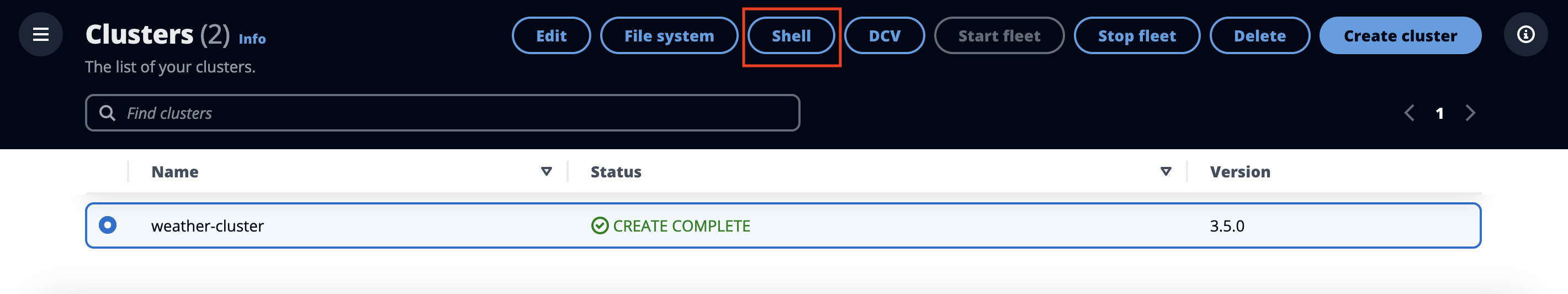
Figure 15. Connect to an HPC cluster - shell.
Option 2: Use NICE DCV Session
After the cluster creation completes, and with the created cluster selected, choose DCV to access the cluster head node:
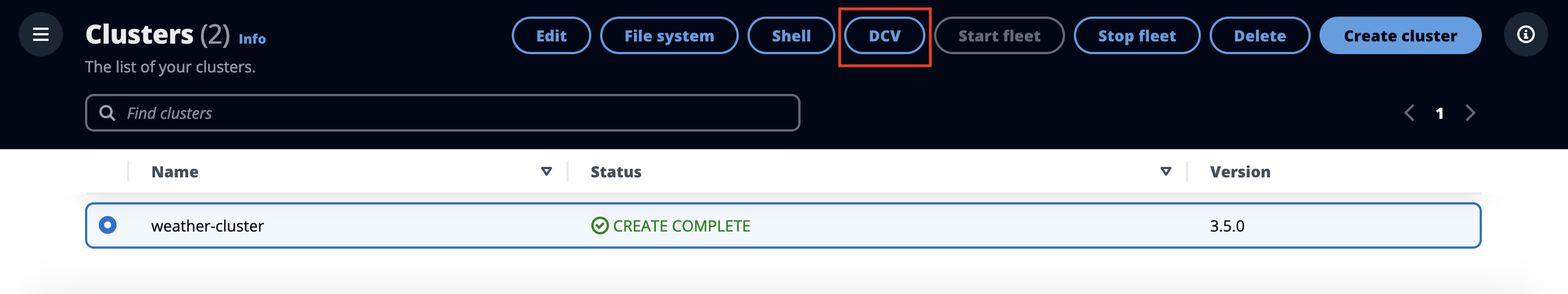
Figure 16. Connect to an HPC cluster - NICE DCV.
A new tab will open.
Your browser may prompt you about the pop-up: select the option to allow pop-ups from the AWS ParallelCluster UI domain.
DCV uses self-signed certificates, and your browser may warn you about a potential security risk. You will need to select Advanced and then Accept the Risk and Continue:
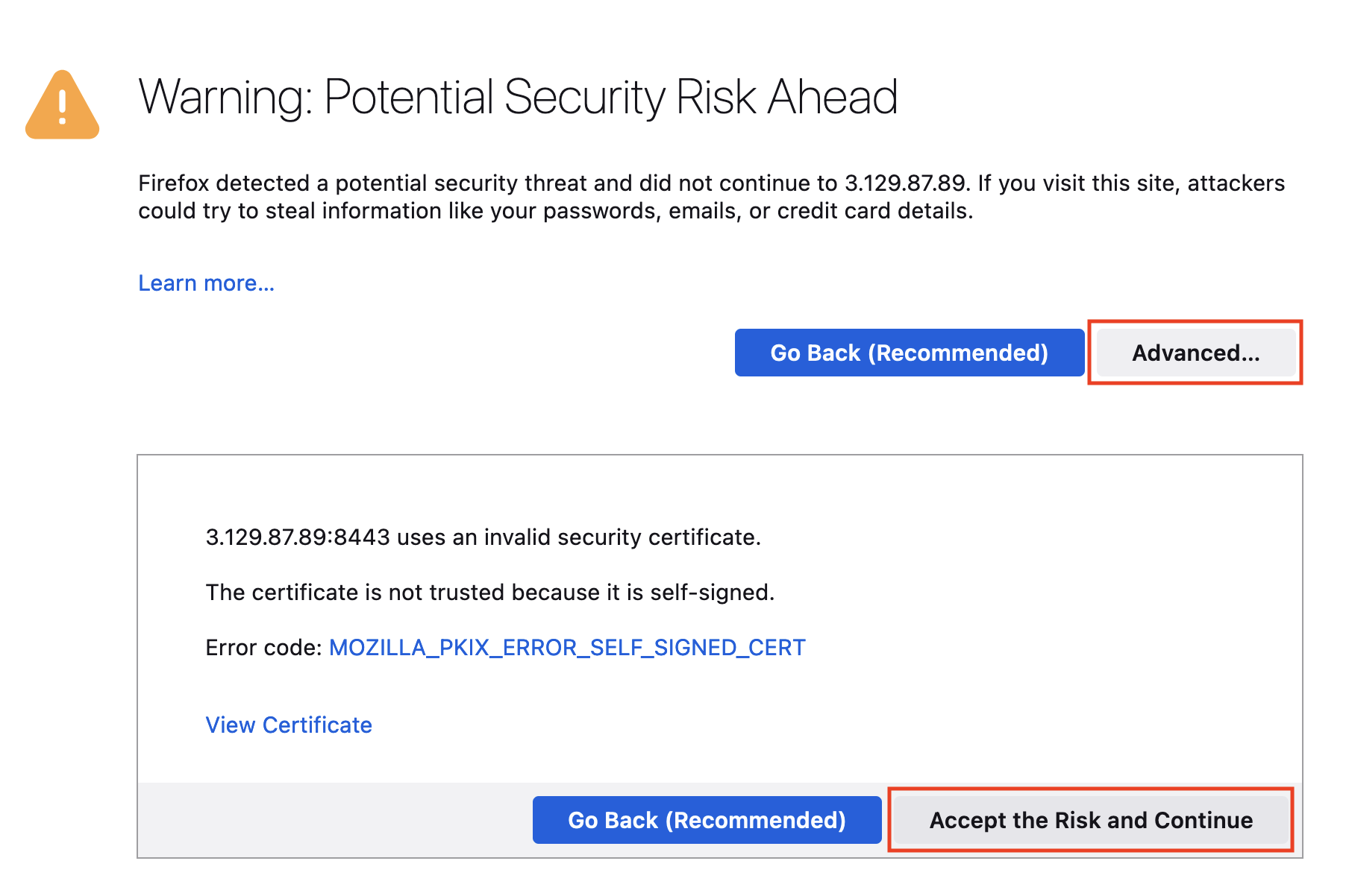
Figure 17. Connect to an HPC cluster - DCV connection pop-up.
To launch a terminal (where the rest of the workshop will run), select Activities, then Terminal:
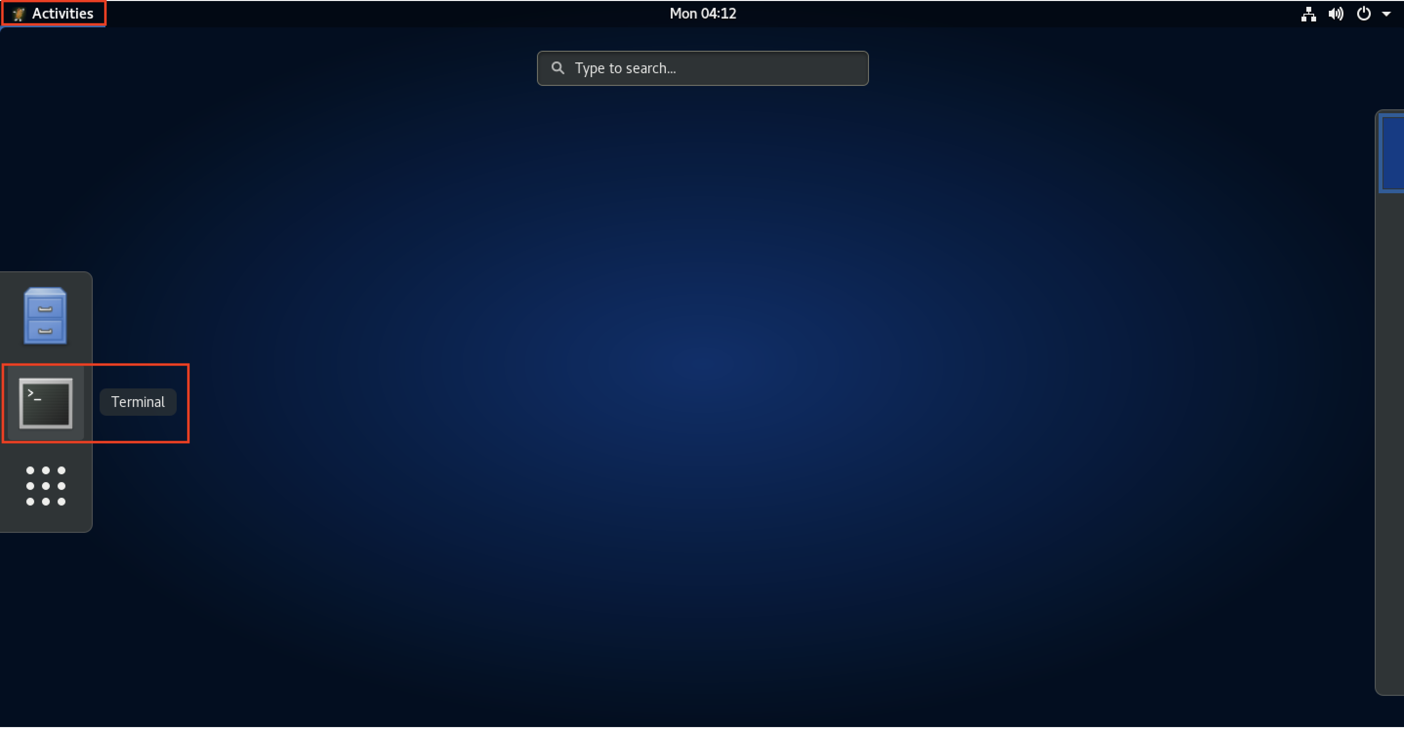
Figure 18. Connect to an HPC cluster - DCV terminal.
The NICE DCV connection is generally less secure than the SSM shell (its IP address is open to the world) and should only be used for tasks that require full GUI support, such as displaying WRF simulation results, that are addressed later in this guide.
- Now that you are connected to the head node, you can familiarize yourself with the cluster structure by running the commands below.
SLURM from SchedMD is a resource manager that you can use in AWS ParallelCluster. For an overview of the SLURM commands, see the SLURM Quick Start User Guide. If you are already familiar with a portable batch system (PBS), refer to the PBS-Slurm Conversion Cheat Sheet.
Your bash user prompt should be similar to ec2-user@ip-<IP-address>. If it is showing up something like sh-4.2 or ssm-user@<IP-address>, then run the following command before proceeding:
sudo su ec2-user

Figure 19. Connect to an HPC cluster - active connection session.
List existing partitions and nodes per partition.
sinfoRunning
sinfoshows both the instances we currently have running and those that are not running (think of this as a queue limit). Initially, we’ll see all the nodes in anidle~state, which means that no instances are running. When we submit a job, we’ll see some instances go into anallocstate, meaning that they’re currently completely allocated, ormix, meaning that some but not all cores are allocated. After the job completes, the instance stays around for a few minutes. The default cooldown is 10 mins in stateidle%. This can be confusing, so we’ve tried to simplify it in the following table:State Description idle~Instance is not running but can launch when a job is submitted. idle%Instance is running and will shut down after Scaledownidletime (default 10 mins). mixInstance is partially allocated. allocInstance is completely allocated. Output:

Figure 20. Head node-sinfo command output.
List jobs in the queues or running. Obviously, there won’t be any since we have not submitted anything yet.
squeueOutput:

Figure 21. Head node-squeue command output.
Module Environment
Environment Modules or Lmod are fairly standard tools in HPC that are used to dynamically change your environment variables (such asPATH and LD_LIBRARY_PATH).
List available modules You’ll notice that every cluster comes with intelmpi and openmpi pre-installed. These message-passing interface (MPI) versions are compiled with support for the high-speed interconnect elastic fabric adapter (EFA).
module availOutput:
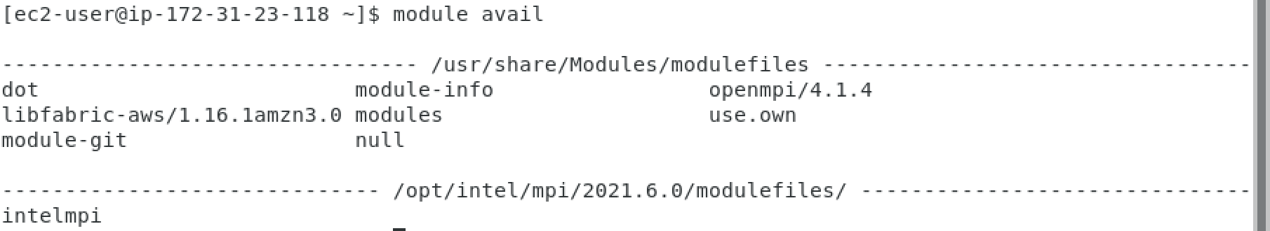
Figure 22. Head node-available modules output.
(OPTIONAL, NOT REQUIRED) - Load a particular MPI module. This command loads Intel MPI in your environment and checks the path of mpirun.
```bash
module load intelmpi
which mpirun
```
**Output**:
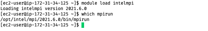
Figure 23. Head node-mpirun command output.
Filesystems
List mounted volumes. A few volumes are shared by the head node through NFS and will be mounted on compute instances when they boot up. Both /fsx and /home are accessible by all nodes.
Check the amount of available disk space for all file systems. When we created the cluster, we also created a Lustre filesystem with FSx for Lustre. We can see where it was mounted and the storage size by running:
df -hTOutput:
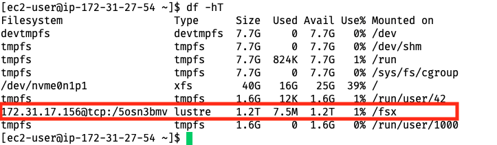
Figure 24. Head node-mounted storage view.
Print the list of exported NFS-based file systems on the head node.
showmount -e localhostOutput:
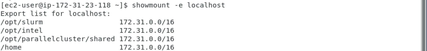
Figure 25. Head node-mounted folder view.
Install Spack Package Manager
Spack is a package manager for supercomputers, Linux, and macOS. It makes installing scientific software easy. Spack isn’t tied to a particular language; you can build a software stack in Python or R, link to libraries written in C, C++, or Fortran, and easily swap compilers or target specific microarchitectures. In this tutorial, we’ll use Spack to compile and install weather codes.
First, on the head node, which we connected to through SSM or DCV, we’ll run the Spack set-up script) by cloning the project repo locally:
  git clone https://github.com/aws-solutions-library-samples/guidance-for-numerical-weather-prediction-with-weather-research-and-forecasting-model-on-aws.git
  cd guidance-for-numerical-weather-prediction-with-weather-research-and-forecasting-model-on-aws
  ./static/set_spack_environment.sh
We can also run commands from that script directly:
 export SPACK_ROOT=/fsx/spack
 git clone -b v0.21.2 -c feature.manyFiles=true https://github.com/spack/spack $SPACK_ROOT
 echo "export SPACK_ROOT=/fsx/spack" >> $HOME/.bashrc
 echo "source \$SPACK_ROOT/share/spack/setup-env.sh" >> $HOME/.bashrc
 source $HOME/.bashrc
 spack --help
In order to make Spack work with the OpenMPI framework, create the following file:
cat > /fsx/spack/etc/spack/packages.yaml <EOF
---  # Zen2/3 packages
packages:
openmpi:
  buildable: false
  externals:
    - prefix: /opt/amazon/openmpi/
      spec: openmpi@4.1.6
  require: ['fabrics=ofi +legacylaunchers schedulers=slurm']
libfabric:
  buildable: false
  externals:
    - prefix: /opt/amazon/efa/
      spec: libfabric@1.19.0
  require: ['fabrics=shm,efa']
pmix:
  require: ["pmix@3:"]
slurm:
  buildable: false
  externals:
    - prefix: /opt/slurm/
      spec: slurm@23.02.7 +pmix
wrf:
 require:
  - one_of: ["wrf@4.5.1 build_type=dm+sm %gcc ^openmpi"]
all:
  compiler: [gcc]
  permissions:
    read: world
    write: user
  providers:
    mpi: [openmpi]
EOF
You can also refer to the GitHub sample code.
Spack Build Cache
We will install the weather codes from a pre-built Spack binary cache or mirror. In order to do this, we need to install a few more Python packages.
pip3 install botocore boto3Next, add the mirror and trust the GNU privacy guard (GPG) keys that have signed the packages. If you want to verify the GPG keys, they are available on OpenGPG. In addition, refer to the sample script.
 spack mirror add v0.21.2 https://binaries.spack.io/v0.21.2
 spack buildcache keys --install --trust --force
We are going to use the GNU Compiler Collection (GCC) already installed. We need Spack to find it by running the following command:
spack compiler find
We will later use GCC to compile binaries, such as WRF, in the next few sections. Once it is complete, we can see the installed package:
Output:
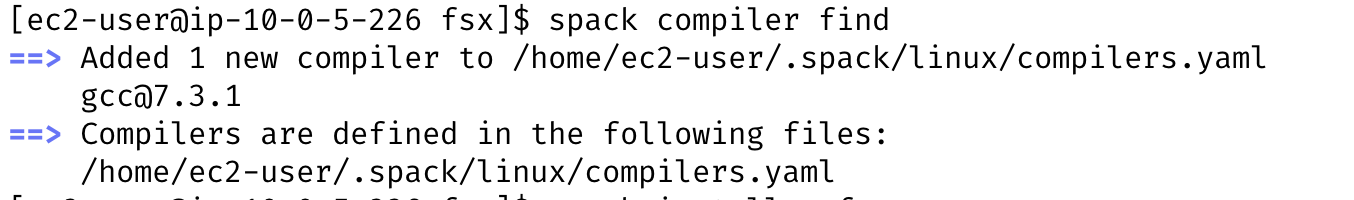
Figure 26. Head node: Spack compiler find output.
Install NCAR Command Language (NCL)
- Next, we’ll install the NCAR Command Language (NCL).
We will use NCL to visualize the output in the next few sections.
spack install ncl^hdf5@1.8.22Spack Flag Description ncl Install the NCL package ^hdf5@1.8.22 Pin the HDF4 dependency at version 1.8.22.
We will also set our default NCL X11 window size to be 1000x1000.
 cat << EOF > $HOME/.hluresfile
 *windowWorkstationClass*wkWidth  : 1000
 *windowWorkstationClass*wkHeight : 1000
 EOF
Install and run Weather Research & Forecasting (WRF)
Now that we’ve built an HPC cluster, we’ll install the WRF framework with the command below, also located in the GitHub repository:
spack install -j $(nproc) wrf build_type=dm+sm
We are installing WRF on the head node. The architecture of the head node instance type, c6a.2xlarge, matches the compute nodes, so Spack does the correct microarchitecture detection. In most other cases, it makes sense to install the WRF package on the compute nodes.
| Spack Flag | Description |
|---|---|
| -j $(nproc) | Compile with all the cores on the HeadNode. |
| build_type=dm+sm | Enable hybrid parallelism MPI + OpenMP. |
This will take about 5 minutes to install. While installation is going, advance to the next steps and Retrieve and deploy the WRF CONUS 12-km model.
To verify the WRF package installation, run the following command:
pack find wrf
-- linux-amzn2-x86_64_v3 / gcc@7.3.1 ----------------------------
wrf@4.5.1
==> 1 installed package
- Retrieve and deploy WRF CONUS 12-km model
Here, we will go through the steps to run the test case(s) provided by NCAR on AWS ParallelCluster. The input data used for simulating the Weather Research & Forecasting (WRF) model is the 12-km CONUS input.
These are used to run the WRF executable wrf.exe to simulate atmospheric events that took place during the Pre-Thanksgiving Winter Storm of 2019. The model domain includes the entire continental United States (CONUS), using 12-km grid spacing, which means that each grid point is 12x12 km. The full domain contains 425 x 300 grid points.
After running the WRF model, post-processing will allow the visualization of atmospheric variables available in the output (such as temperature, wind speed, and pressure).
Retrieve the CONUS 12-km model data:
cd /fsx
curl -O https://www2.mmm.ucar.edu/wrf/OnLineTutorial/wrf_cloud/wrf_simulation_CONUS12km.tar.gz
tar -xzf wrf_simulation_CONUS12km.tar.gz
Prepare the data for a run by copying in the relevant files from the WRF install:
cd /fsx/conus_12km/
WRF_ROOT=$(spack location -i wrf)/test/em_real/
ln -s $WRF_ROOT* .
Be aware that there is a
namelist.inputin the current directory that you do not want to overwrite. The link command will return the following error, which is safe to ignore:ln: failed to create symbolic link ‘./namelist.input’: File exists
Sample code that automates the scripts above can be found with the sample code.
- Start WRF batch job processing and monitor the results.
- Create a Slurm sbatch script to run the CONUS 12-km model:
cd /fsx/conus_12km/
cat > slurm-wrf-conus12km.sh << EOF
#!/bin/bash

#SBATCH --job-name=WRF
#SBATCH --output=conus-%j.out
#SBATCH --nodes=2
#SBATCH --ntasks-per-node=48
#SBATCH --exclusive
#SBATCH --cpus-per-task=2

spack load wrf
module load libfabric-aws
wrf_exe=$(spack location -i wrf)/run/wrf.exe
set -x
ulimit -s unlimited
ulimit -a

export OMP_NUM_THREADS=2
export FI_PROVIDER=efa
export KMP_AFFINITY=compact
echo " Will run the following command: time mpirun --report-bindings --bind-to core --map-by slot:pe=${OMP_NUM_THREADS} $wrf_exe"
time mpirun --report-bindings --bind-to core --map-by slot:pe=${OMP_NUM_THREADS} $wrf_exe
EOF
Refer to the sample script which can be adjusted for various processor cores by using #SBATCH settings and other options.
In the above job script, we’ve set the environment variables to ensure that MPI and OpenMP are pinned to the correct cores and EFA is enabled.
| Environment Variable | Value |
|---|---|
OMP_NUM_THREADS=2 | Number of OpenMP threads. We’re using 48 MPI procs, each with 2 open multi-processing (OMP) threads to use all 48 x 2 = 96 cores. |
FI_PROVIDER=efa | Enable EFA. This tells libfabric to use the EFA fabric. |
KMP_AFFINITY=compact | Specifying compact assigns the OpenMP thread N+1 to a free thread context as close as possible to the thread context where the N OpenMP thread was placed. |
Submit the job; you can refer to the sample command with debug echo options):
sbatch slurm-wrf-conus12km.sh
Monitor the job’s status using the
squeuecommand:squeueYou might see that the cluster initially doesn’t have compute node capacity to complete the job, so those compute nodes will have to get provisiond first:
JOBID PARTITION NAME USER ST TIME NODES NODELIST(REASON) 1 compute WRF ec2-user PD 0:00 2 (Nodes required for job are DOWN, DRAINED or reserved for jobs in higher priority partitions) You can also set an auto-refresh for an output of
squeuecommand by running it with the following option of auto-refresh interval:squeue -i 2
You can also monitor the provisoning of the requested number (2 in our example) and type (per cluster specification) of the HPC cluster compute nodes instances in the EC2 console:

Figure 27. Compute Nodes dynamically provisoned for running WRF job
Once the nodes are provisioned and the required compute capacity is available, the job will be processed and you may get a confirmation message like the following:
Using 192 cores, the job took 4 mins 17 seconds to complete.
A detailed output of the batch job can be found in the output log file, simarly named /fsx/conus_12km/conus-5.out and shown below:
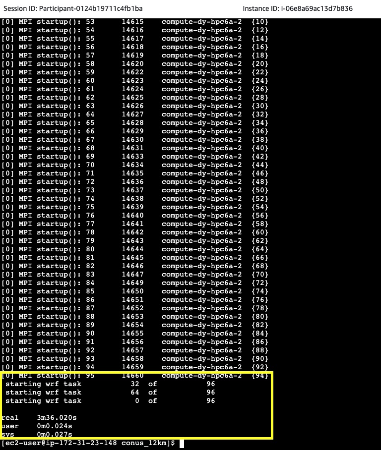
Figure 28. Sample conus-X.out file contents
That information can be used for troubleshooting the batch job processing.
You can also monitor a submitted job status through the ParallelCluster UI using the Job Status menu and observe the status of a job:
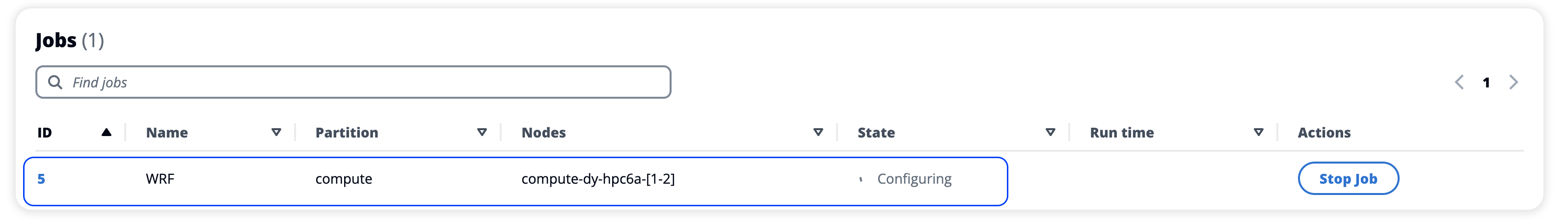
Figure 29. Sample WRF job summary
Or, monitor individual job processing details by selecting on a link:
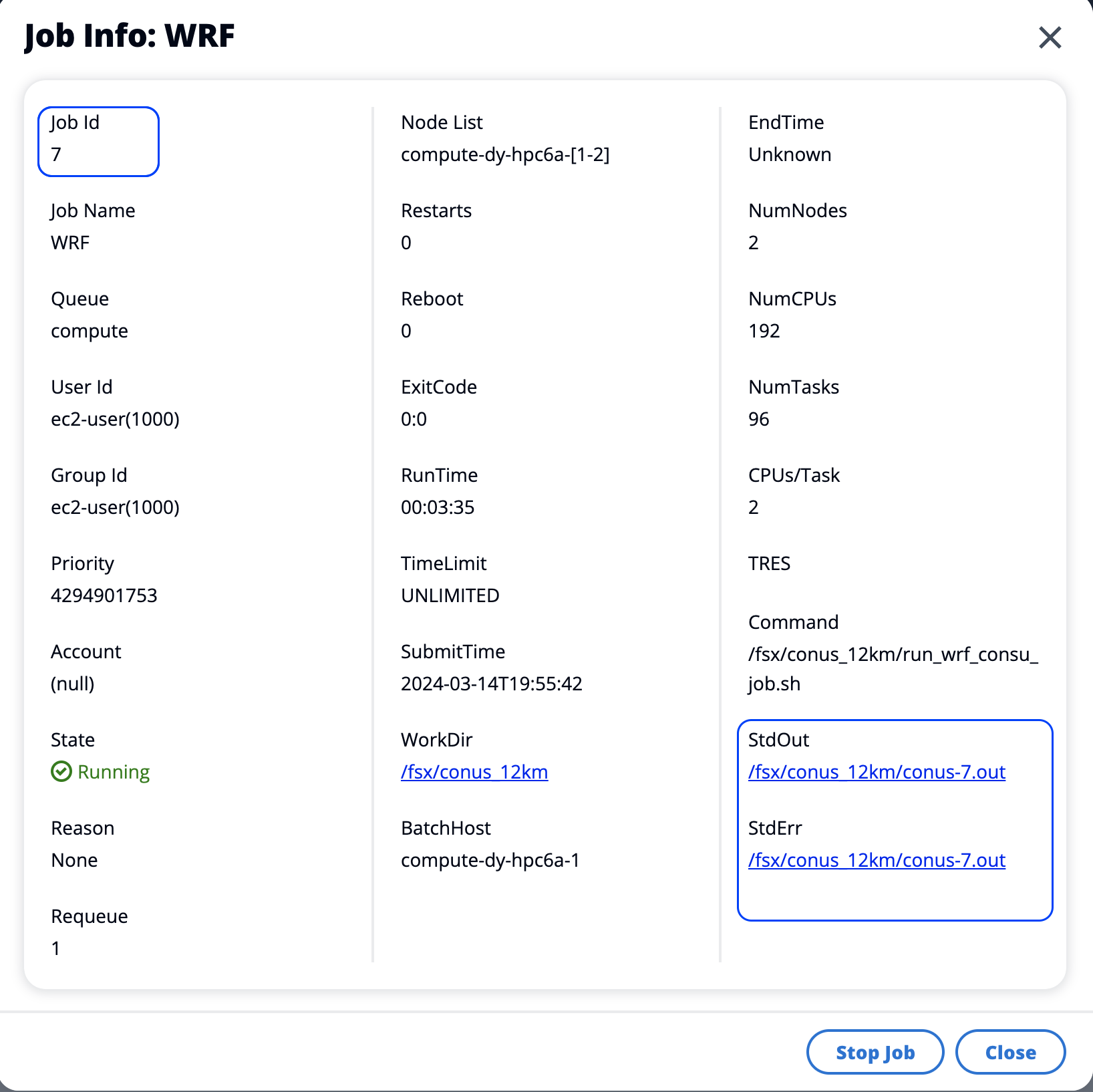
Figure 30. Sample WRF job details
- Visualize simulation results
In this section, we’re going to visualize the results of the job we just ran using NCL. Ensure that you have completed the steps for preparing and creating an HPC Cluster before proceeding.
Use the NICE DCV connection option (instead of Shell) to access your head node for this section.
Navigate to the WRF run directory:
cd /fsx/conus_12kmThe provided
ncl_scripts/surface.nclscript will generate two plots of surface fields at a valid time of 2019-11-27 00:00. Use the space bar to advance to the next plot.ncl ncl_scripts/surface.ncl
Output: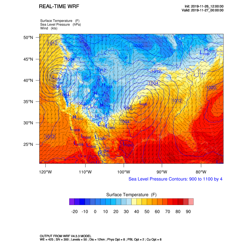
Figure 31. Sample WRF surface temperature forcecast
Generate a vertical profile of relative humidity (%) and temperature (K):
ncl ncl_scripts/vert_crossSection.nclOutput:
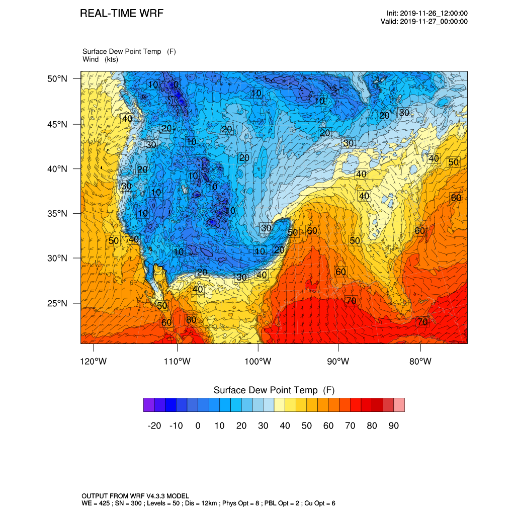
Figure 32. Sample WRF surface dew point temperature forcecast
Cleanup Running Jobs and Stop Cluster
To stop the cluster and any running jobs, select the Stop Fleet on the cluster detail pane:
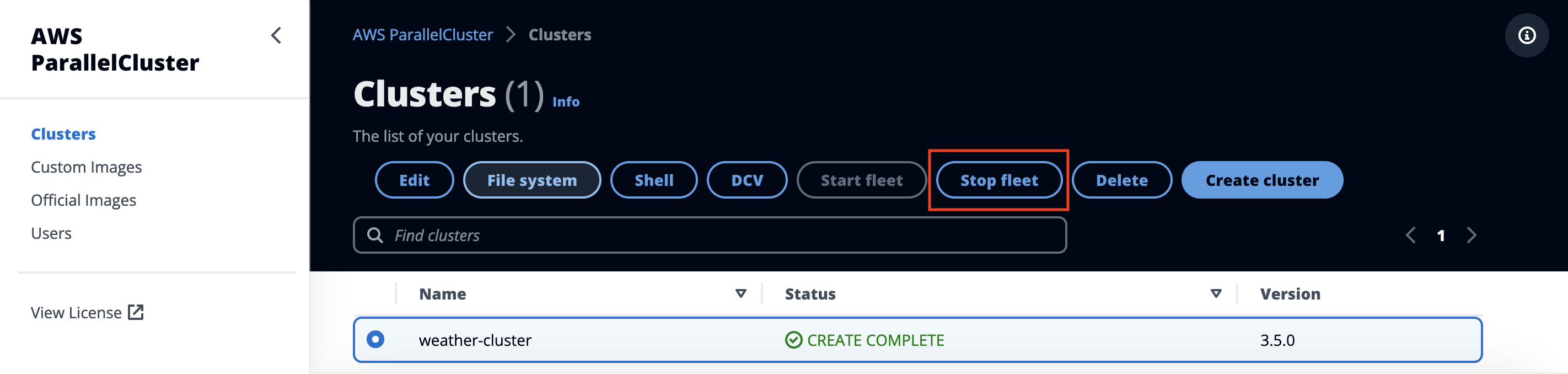
Figure 33. Cleanup - stop cluster
Next, select the Instances tab and stop the head node by selecting Stop.
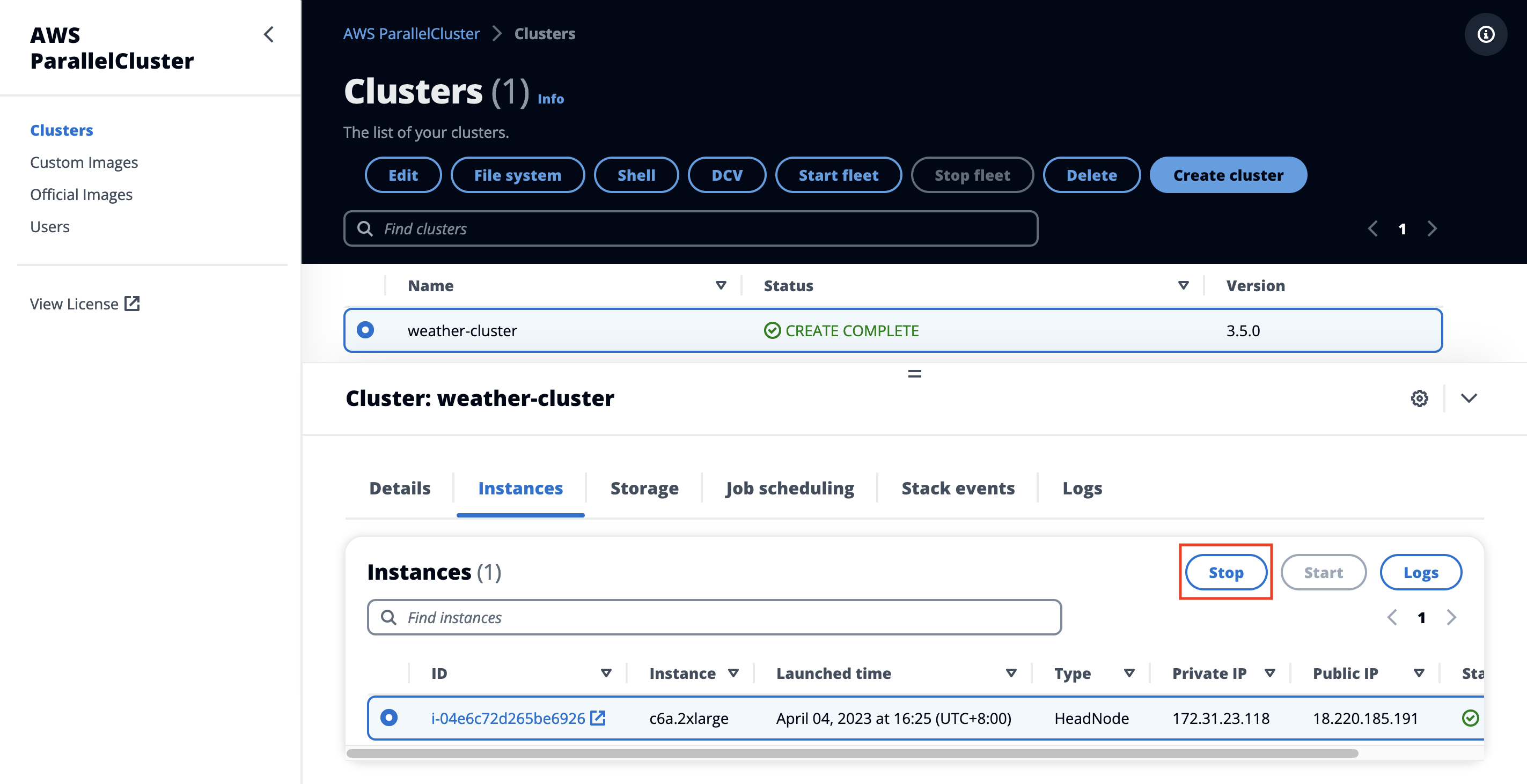
Figure 34. Cleanup-stop head node
Now your cluster is stopped! To resume at a later time, start the head node, then the corresponding cluster.
Uninstall the Guidance
You can uninstall the Guidance for Building a High-Performance Numerical Weather Prediction System on AWS using the ParrallelCluster UI from the AWS Management Console, or by using the AWS Command Line Interface (CLI).
You must manually delete the users created by this Guidance in Amazon Cognito.
Below are the steps to uninstall:
To stop the cluster and any running jobs, select the Stop Fleet on the cluster detail pane:
Figure 35. Cleanup-stop cluster fleet
Next, select the Instances tab and stop the head node by selecting Stop.
Figure 36. Cleanup-stop head node
Delete the HPC Cluster
To delete the cluster, select Delete on the cluster detail pane. You will be prompted for confirmation.
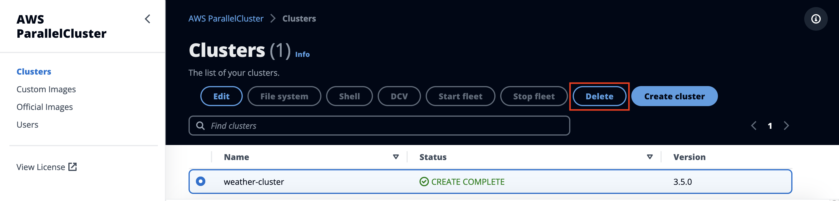
Figure 37. Cleanup-delete HPC cluster
- Delete the AWS ParallelCluste UI
In the AWS Management Console, navigate to the CloudFormation page. Select the AWS ParallelCluster UI stack (STACK_NAME in previous steps), and choose Delete.
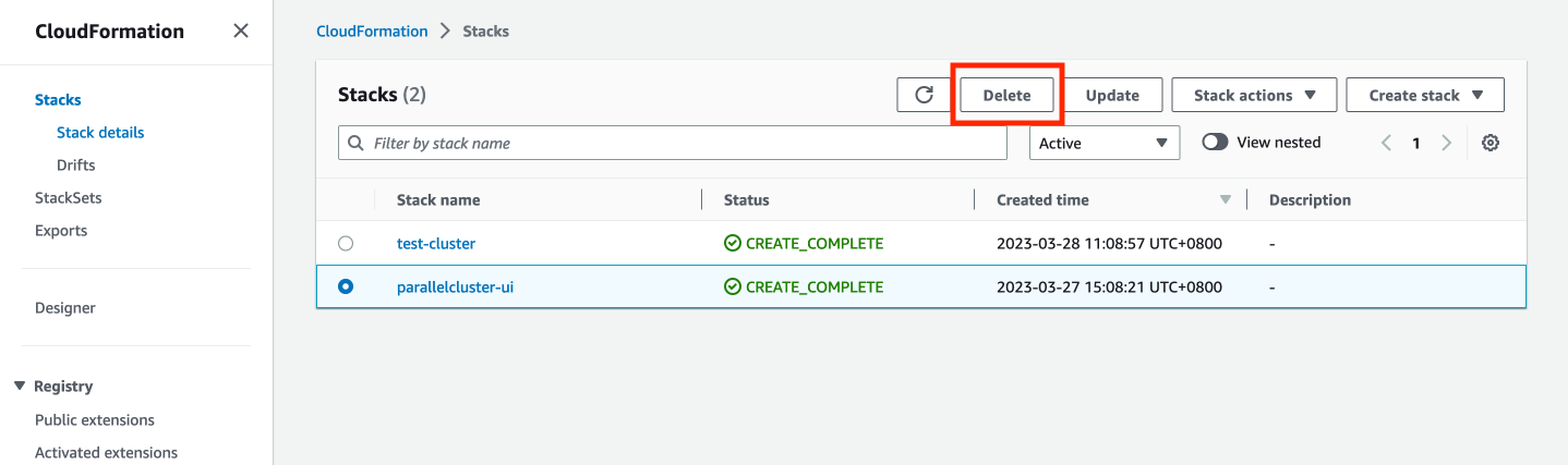
Figure 38. Cleanup - delete Parallel Cluster UI
Support & Feedback
Guidance for Building a High-Performance Numerical Weather Prediction System on AWS is an Open Source project maintained by AWS Solution Architects. It is not part of an AWS Services and support is provided best-effort by AWS Solution Architects and the users community.
To post feedback, submit feature ideas, or report bugs, you can use the Issues section of the project GitHub repo and the Guidance page. If you are interested in contributing to the sample code, you can follow the Contribution process.
Related Resources
- Amazon High Performance Computing
- Amazon Elastic Fabric Adapter (EFA)
- Public HPC Weather Prediction Workshop Studio Catalog
- AWS ParallelCluster UI
- Spack package manager
- GNU Compiler Collection
- NCAR Command Language (NCL) overview
- Weather Research & Forecasting model
- Benchmark test cases overview
Contributors
- Daniel Zilberman, Senior SA, Tech Solutions team
- Timothy Brown, Principal SA, HPC Solutions team
Notices
Customers are responsible for making their own independent assessment of the information in this document. This document: (a) is for informational purposes only, (b) represents AWS current product offerings and practices, which are subject to change without notice, and (c) does not create any commitments or assurances from AWS and its affiliates, suppliers or licensors. AWS products or services are provided “as is” without warranties, representations, or conditions of any kind, whether express or implied. AWS responsibilities and liabilities to its customers are controlled by AWS agreements, and this document is not part of, nor does it modify, any agreement between AWS and its customers.